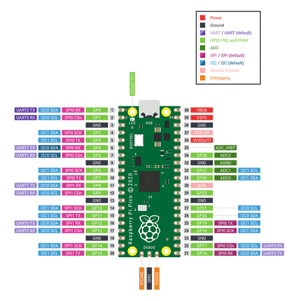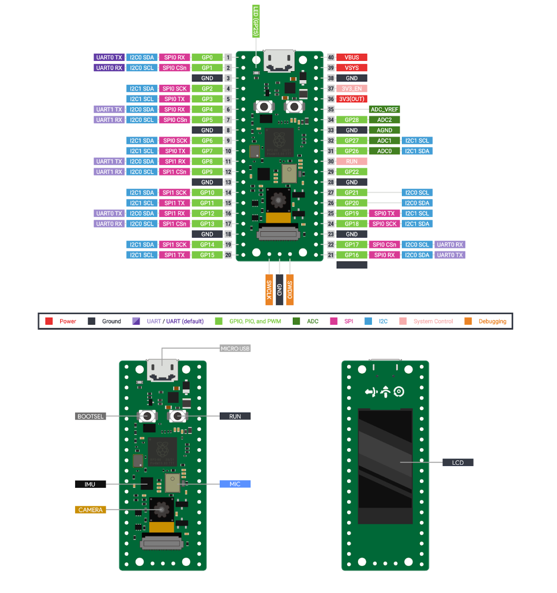

Moreover, it can also be driven with interrupt or DMA. It has 8 buffers for each transmitter and receiver of the SPI controller. National Semiconductor Serial Interface.SPI ControllerĮach SPI controller supports master and slave mode and are compatible with the following four modes: But before using SPI, you should configure in software which GPIO pins you want to use with a specific SP peripheral. Each connection of SPI controller pins can be configured through multiple GPIO pins as shown in the figure.

The following table shows the connection of GPIO pins with both SPI modules. Both SPI module pins are accessible through GPIO pins of Raspberry Pi Pico. RP2040 chip supports two SPI peripherals.

But before using an I2C controller, you should configure in software which GPIO pins you want to use with a specific I2C controller. Each connection of the controller can be configured through multiple GPIO pins as shown in the figure. The following table shows the connection of GPIO pins with both I2C controllers. Both I2C controllers are accessible through GPIO pins of Raspberry Pi Pico. Raspberry Pi Pico ADC with Voltage Measurement Examples.Therefore, the sampling frequency is 96 x 1 / 48MHz) = 2 μs per sample (500kS/s).Ĭheck this Raspberry Pi Pico ADC tutorial:

ADC takes 96 CPU clock cycles to perform one conversion. Because RP2040 microcontroller operates on 48MHZ clock frequency which comes from USB PLL. ADC ModuleĪ/D conversion can be performed in polling, interrupt, and FIFO with DMA mode.ĪDC conversion speed per sample is 2μs that is 500kS/s. The following table shows that the input signal for ADC0, ADC1, and ADC2 can be connected with GP26, GP27, and GP28 pins, respectively. Therefore, if we want to measure temperature, we can directly use build-in temperature by reading the analog value of ADC4. The fourth analog channel is internal connected to the internal temperature sensor. But only three analog channels are exposed to pinout. It supports four 12-bit SAR based analog to digital converters.


 0 kommentar(er)
